LTC3541
3541fa
PPLICATIO S I FOR ATIO
U
U
be obtained by choosing an output capacitor value of 10礔
to 22礔. Typically, once the ESR requirement for C
OUT
has
been met, the RMS current rating generally far exceeds
the I
RIPPLE(P-P)
requirement. The output ripple 擵
OUT
is
determined by:
E?nbsp +
?/DIV>
?/DIV>
?/DIV>
?/DIV>
?/DIV>
?/DIV>
V I ESR
fc
OUT L
OUT
1
8
where f = operating frequency, C
OUT
= output capacitance
and 擨
L
= ripple current in the inductor. For a fixed output
voltage, the output ripple is highest at maximum input
voltage since 擨
L
increases with input voltage.
Aluminum electrolytic and dry tantalum capacitors are both
available in surface mount configurations. In the case of
tantalum, it is critical that the capacitors are surge tested
for use in switching power supplies. An excellent choice is
the AVX TPS series of surface mount tantalum. These are
specially constructed and tested for low ESR so they give
the lowest ESR for a given volume. Other capacitor types
include Sanyo POSCAP, Kemet T510 and T495 series, and
Sprague 593D and 595D series. Consult the manufacturer
for other specific recommendations.
Using Ceramic Input and Output Capacitors
High value, low cost ceramic capacitors are now becoming
available in smaller case sizes. Their high ripple current,
high voltage rating, and low ESR make them ideal for
switching regulator applications. Since the LTC3541s
control loop does not depend on the output capacitors
ESR for stable operation, ceramic capacitors can be used
freely to achieve very low output ripple and small circuit
size.
However, care must be taken when ceramic capacitors
are used at the input and the output. When a ceramic
capacitor is used at the input and the power is supplied
by a wall adapter through long wires, a load step at the
output can induce ringing at the input, V
IN
. At best, this
ringing can couple to the output and be mistaken as loop
instability. At worst, a sudden inrush of current through
the long wires can potentially cause a voltage spike at V
IN
,
large enough to damage the part.
When choosing the input and output ceramic capacitors,
choose the X5R or X7R dielectric formulations. These
dielectrics have the best temperature and voltage charac-
teristics of all the ceramics for a given value and size.
Output Voltage Programming
The output voltage is set by tying BUCKFB to a resistive
divider according to the following formula:
V
R
R
OUT
= +
?/DIV>
?/DIV>

?/DIV>
?/DIV>
?/DIV>
?/DIV>
08 1
2
1
.
Since the impedance at the BUCKFB pin is dependant upon
the resistor divider network used, and phase shift due to
this impedance directly impacts the transient response of
the buck, R1 should be chosen <125k. In addition, stray
capacitance at this pin should be minimized (<5pF) to pre-
vent excessive phase shift. Finally, special attention should
be given to any stray capacitances that can couple external
signals onto the BUCKFB pin producing undesirable output
ripple. For optimum performance connect the BUCKFB
pin to R1 and R2 with a short PCB trace and minimize all
other stray capacitance to the BUCKFB pin.
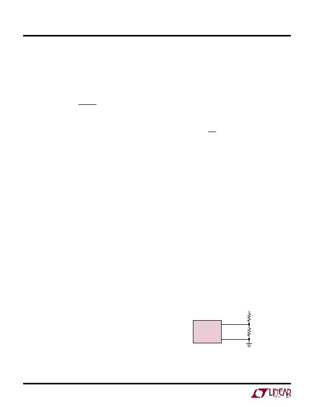
The external resistive divider is connected to the output,
allowing remote voltage sensing as shown in Figure 6.
Checking Transient Response
The regulator loop response can be checked by looking
at the load transient response. Switching regulators take
several cycles to respond to a step in load current. When
a load step occurs, V
OUT
immediately shifts by an amount
equal to (擨
LOAD
" ESR), where ESR is the effective series
Figure 6. Setting the LTC3541 Output Voltage
BUcKFB
GND
LTc3541
0.8V d V
OUT
d 5V
R2
R1
发布紧急采购,3分钟左右您将得到回复。
相关PDF资料
LTC3670EDDB#TRPBF
IC REG TRPL BCK/LINEAR 12DFN
LTC3672BEDC-1#TRPBF
IC REG TRPL BCK/LINEAR 8-DFN
LTC3700EMS#TRPBF
IC REG DL BUCK/LINEAR 10MSOP
LTC4151HMS#TRPBF
IC PWR MONITOR MS 80V SD 10MSOP
LTC4210-2CS6#TRM
IC CONTROLLER HOT SWAP TSOT23-6
LTC4211IMS8
IC CONTROLLER HOT SWAP 8-MSOP
LTC4212IMS#TRPBF
IC CTRLR HOTSWAP TIMEOUT 10MSOP
LTC4214-1IMS#TRPBF
IC CTRLR HOTSWAP NEGVOLT 10MSOP
相关代理商/技术参数
LTC3541EDD-1#PBF
功能描述:IC REG DL BCK/LINEAR SYNC 10-DFN RoHS:是 类别:集成电路 (IC) >> PMIC - 稳压器 - 线性 + 切换式 系列:- 标准包装:2,500 系列:- 拓扑:降压(降压)同步(3),线性(LDO)(2) 功能:任何功能 输出数:5 频率 - 开关:300kHz 电压/电流 - 输出 1:控制器 电压/电流 - 输出 2:控制器 电压/电流 - 输出 3:控制器 带 LED 驱动器:无 带监控器:无 带序列发生器:是 电源电压:5.6 V ~ 24 V 工作温度:-40°C ~ 85°C 安装类型:* 封装/外壳:* 供应商设备封装:* 包装:*
LTC3541EDD-1#TRPBF
功能描述:IC REG DL BCK/LINEAR SYNC 10-DFN RoHS:是 类别:集成电路 (IC) >> PMIC - 稳压器 - 线性 + 切换式 系列:- 标准包装:2,500 系列:- 拓扑:降压(降压)同步(3),线性(LDO)(2) 功能:任何功能 输出数:5 频率 - 开关:300kHz 电压/电流 - 输出 1:控制器 电压/电流 - 输出 2:控制器 电压/电流 - 输出 3:控制器 带 LED 驱动器:无 带监控器:无 带序列发生器:是 电源电压:5.6 V ~ 24 V 工作温度:-40°C ~ 85°C 安装类型:* 封装/外壳:* 供应商设备封装:* 包装:*
LTC3541EDD-1-PBF
制造商:LINER 制造商全称:Linear Technology 功能描述:High Efficiency Buck + VLDO Regulator
LTC3541EDD-1-TRPBF
制造商:LINER 制造商全称:Linear Technology 功能描述:High Efficiency Buck + VLDO Regulator
LTC3541EDD-2
制造商:LINER 制造商全称:Linear Technology 功能描述:High Efficiency Buck + VLDO Regulator
LTC3541EDD-2#PBF
功能描述:IC REG DL BCK/LINEAR SYNC 10-DFN RoHS:是 类别:集成电路 (IC) >> PMIC - 稳压器 - 线性 + 切换式 系列:- 标准包装:2,500 系列:- 拓扑:降压(降压)同步(3),线性(LDO)(2) 功能:任何功能 输出数:5 频率 - 开关:300kHz 电压/电流 - 输出 1:控制器 电压/电流 - 输出 2:控制器 电压/电流 - 输出 3:控制器 带 LED 驱动器:无 带监控器:无 带序列发生器:是 电源电压:5.6 V ~ 24 V 工作温度:-40°C ~ 85°C 安装类型:* 封装/外壳:* 供应商设备封装:* 包装:*
LTC3541EDD-2#TRPBF
功能描述:IC REG DL BCK/LINEAR SYNC 10-DFN RoHS:是 类别:集成电路 (IC) >> PMIC - 稳压器 - 线性 + 切换式 系列:- 标准包装:2,500 系列:- 拓扑:降压(降压)同步(3),线性(LDO)(2) 功能:任何功能 输出数:5 频率 - 开关:300kHz 电压/电流 - 输出 1:控制器 电压/电流 - 输出 2:控制器 电压/电流 - 输出 3:控制器 带 LED 驱动器:无 带监控器:无 带序列发生器:是 电源电压:5.6 V ~ 24 V 工作温度:-40°C ~ 85°C 安装类型:* 封装/外壳:* 供应商设备封装:* 包装:*
LTC3541EDD-3
制造商:LINER 制造商全称:Linear Technology 功能描述:High Efficiency Buck + VLDO Regulator
